 En
En
 Th
Th
 RU
RU


Technologies
SMC offers a wide range of High Speed Extrusion Blow Moulding Machines as well as a multiple choice of operational standard accessories and auxiliary equipment. The wide variety of extrusion heads, extruders, clamping units and accessories will allow the users to choose the most suitable set up of production for their machines..
READ MORE
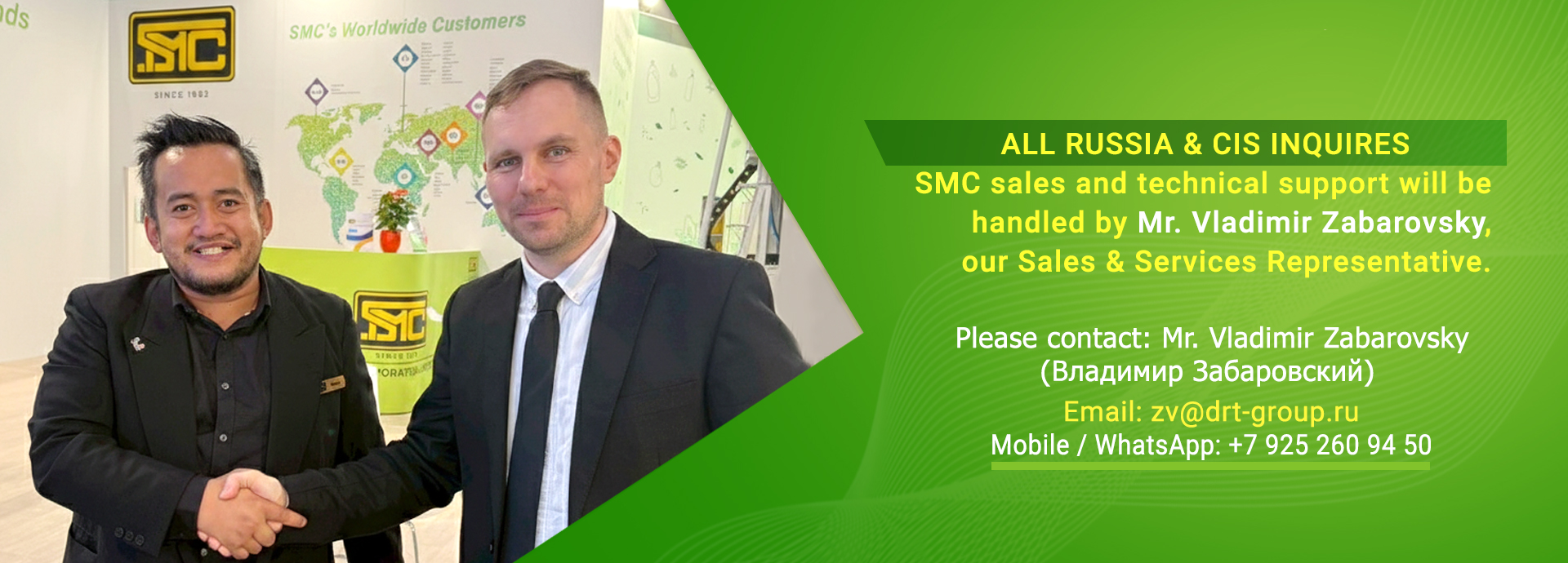
Sales & Service Representatives
SMC Corporation Limited is satisfying customers around the world beginning in its origin, Thailand, expanding via Asian neighbors and now through-out the world.
SMC has served foreign and domestic markets and has continued to provide business opportunities more than 70 counties around the globe.


SMC CORPORATION LIMITED
OFFICE
-
 243 Soi Noppakao 5
Prachachuen Road,
Bangsue, Bangsue,
Bangkok 10800 THAILAND -

-

-

FACTORY
-
66/2, Mou. 15, Takhram-En,
Thamaka, Kanchanaburi
71130 THAILAND
-
-
-